Motor Mapping: Incorporating Accelerometer
Using a single two-axis accelerometer control the movements of the boat depended on some pretty complex motor mapping. Of course, the end goal was to come up with an x-y map that corresponded to a certain left and right motor speed. We tested a lot with different kinds of motor mappings, and we ended up going with something similar to what we did last quarter. Below is a detail description of what we did.
X-Y Accelerometer Output to Direction-Power
Our motor mapping first takes a polar coordinate approach, in which we use the "distance/radius" from the equilibrium (2.5V,2.5V) to determine power, and we use angle to determine direction. Below shows how to find power and direction:

Unfortunately this approach requires the use of functions such arctan and sqrt. We tried using those functions given by math.h, but they ended up taking approximately 60% of program and memory space. Instead we used some approximation functions.
For finding the square root (and subsequently power), we do the following, where R^2 (x^2+y^2) is the number we want to find the square root of (if you notice the first function will give us a dead-band, which we might want, since for values of x less than approximately 40, the int becomes truncated. Coefficients are based on the fact that the A/D converter will give us numbers between 0 and 255 for both x and y coordinates, which we translate to -127 to 127):
For finding the square root (and subsequently power), we do the following, where R^2 (x^2+y^2) is the number we want to find the square root of (if you notice the first function will give us a dead-band, which we might want, since for values of x less than approximately 40, the int becomes truncated. Coefficients are based on the fact that the A/D converter will give us numbers between 0 and 255 for both x and y coordinates, which we translate to -127 to 127):


For finding direction, instead of trying to be linear with respect to
theta, we use cos (which is just x/R, where R is the power we just found), which gives us the same extreme limits, but gives us
less sensitivity near the equilibrium position. This might or might not
be an undesirable effect; we will have to see, but this is a lot easier
to calculate. The graph below shows direction being linear with theta,
and the difference of using cos.

Direction-Power to Left-Right Motor Speeds
We then use the motor mapping from last quarter to convert the newly found direction and power to the left and right motor speeds. The motor mapping is shown below.
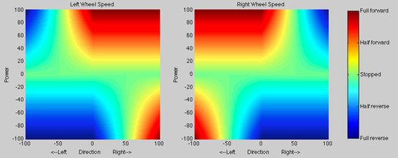
X-Y Accelerometer Output to Left-Right Motor Speeds
Using the two mapping above we can combine them to look at the overall motor mapping that we were looking for:

Problems with Motor Mapping: Incorporating Buttons
This motor mapping is not exactly what we wanted, and the problem lies when tilting the accelerometer back. Intuitively you would want the boat to go in reverse, which it does. However, for example, when tilting back and to the right, this motor mapping shows that the left wheel would be stopped and the right wheel goes in reverse. This makes the boat go back and to the left; intuitively you want the boat to go back and to the right. Unfortunately incorporating this type of mapping in a continuous fashion yields and non-symmetrical result, which is shown here in a blog post. There were also problems with this too since the transitions were too harsh. We elected to go with the unintuitive motor mapping, except that one of our sensing modes was a button that would switch the left and right motor speeds, which would give the user a more familiar behavior when going in reverse.
Scaling Power: Incorporating Force Sensitive Resistor
We scaled the power, calculated in the accelerometer mapping, using the force sensitive resistors (FSR). In a nutshell, if one is not pressing the FSR the power is 0. If one is pressing somewhere in between 0 and 100 percent, the power is a fraction of what is calculated from the motor mapping with the accelerometer. And in the last case if the FSRs are pressed fully it responds like what the motor mapping shows above. The graph below shows what we implemented. We wanted the boat to be able to go at 80% of the calculated power if the FSR is halfway pressed (2.5V). The scaling factor reaches 100% at 3.2V and beyond.

