Sensing Inputs
Our project used three sensing modes: (1) accelerometer, (2) force sensitive resistors, and (3) push buttons. Below is a description of each. To see how we mapped these sensing inputs into software to drive the boat, please see our control algorithm.
Accelerometer
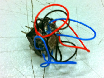
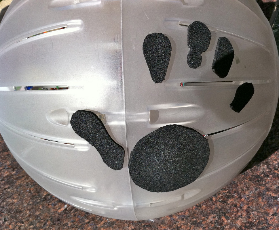
Our accelerometer mounted to a 8-pin DIP
A 2-axis accelerometer (ADXL203) was used as a way to map the ACV's direction, as well as a way to indicate power (in conjunction with the force sensitive resistor). We actually made the breakout board for the ADXL203, as a cost-cutting strategy, since we received the accelerometer as a sample. 30 gauge wire was soldered onto the pads. We then hot glued the accelerometer-wire assembly onto a 8-pin DIP socket and soldered the other ends of the wires into each individual pin hole. The final assembly is seen to the right (it usually has a PVC pipe protective shell). We actually thought we would be the first ones to do this (at least on the ADXL203), but after a quick random youtube search of ADXL203, we found out that we were sadly not (see first 3 secs and the much better craftsmanship): http://www.youtube.com/watch?v=-KyGC8TIoCE
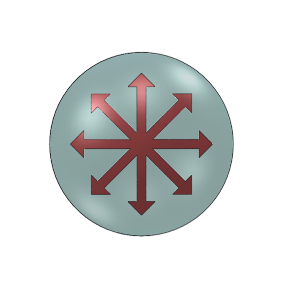
Top view of CVC
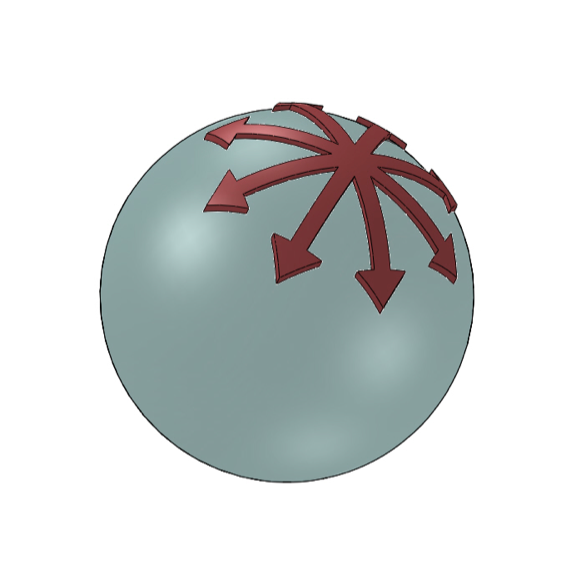
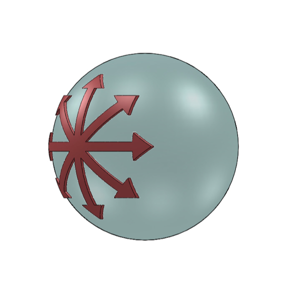
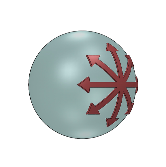
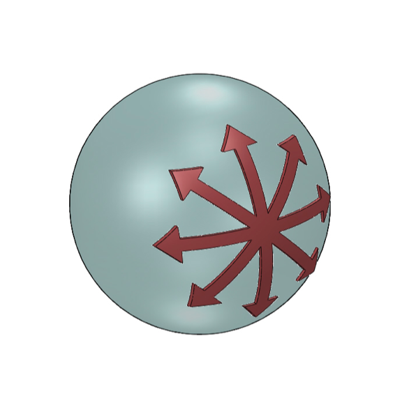
So how does this work? We tried to make the motions as intuitive as possible. The accelerometer is positioned in the middle of our chinchilla ball. Referring to the left picture, if we imagine that we are looking at the top of the chinchilla ball (in reality this would be the atoll score plate), then we expect that the movements about the ball's centroid shown in the pictures below should correspond to the directional behaviors written in the captions. Tilting the ball further in these directions correspond to more power (please see force sensitive resistor section for further information about power). Our CVC-ACV coupling follows these behaviors, except in the situations with an asterisk (*), in which case you have to press the push button, which we explain in the motor mapping section, as well as the push-button section.
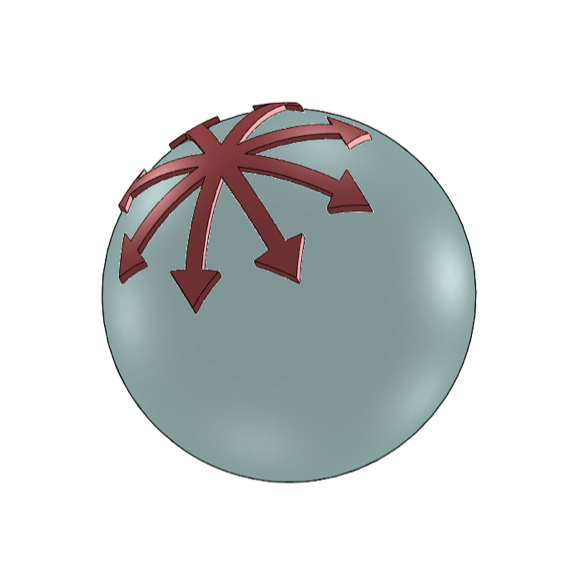
Left turn, pivoting on left wheel
Forward
Right turn, pivoting on right wheel
Left turn in place

Stopped
Right turn in place
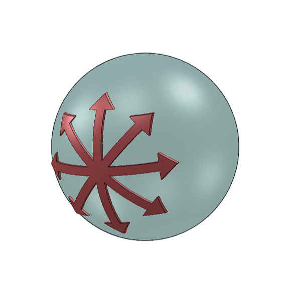
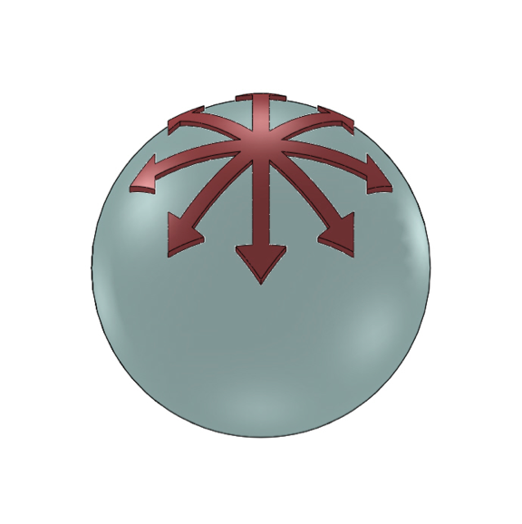
Right turn, pivoting on left wheel (*)
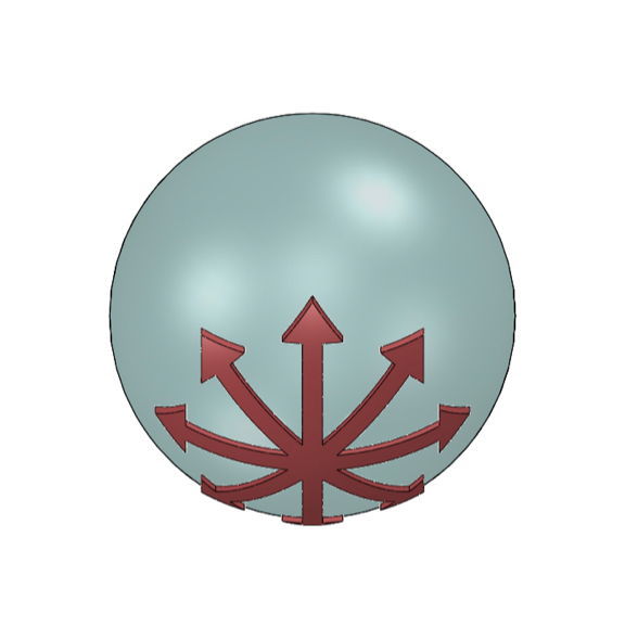
Reverse
Left turn, pivoting on right wheel (*)
(*) Push Buttons
In order to achieve the correct behavior when the ball is pointed back and to the left/right, as explained above, one needs to press either one of two buttons under the thumb pads. This swaps the motor commands of the left and right motors (so left becomes right and vice versa). Even in the case where you are not pointing the ball and to the left/right, you can imagine that these push button might give you some interesting behavior. For example, if you were turning right, but did not mean to, you could just press the button and it will turn you left instead.
Force Sensitive Resistor
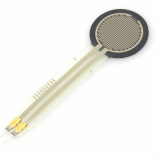
Force sensitive resistors (FSRs) were put under each of the palm pads. The force (a combination of both FSRs) scales, as a fraction, the power that was calculated from the accelerometer motor mapping. For example, if the controller was pointed half forward, and the FSR output specified 100%, then the boat would go at forward at half speed. If the FSR output specified 50%, then the boat would drive at 25% forward. Please see our Control Algorithm section to see how we mapped our circuit output to speed amplification. Please see our CVC Electronics section to see the transresistance circuit we used to map the FSRs' resistance change to a voltage output.
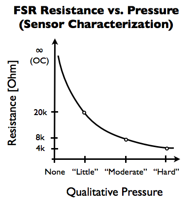
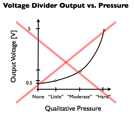
A simple voltage divider does not give an output that scales well with applied pressure because of the several orders of magnitude that the FSR output covers.
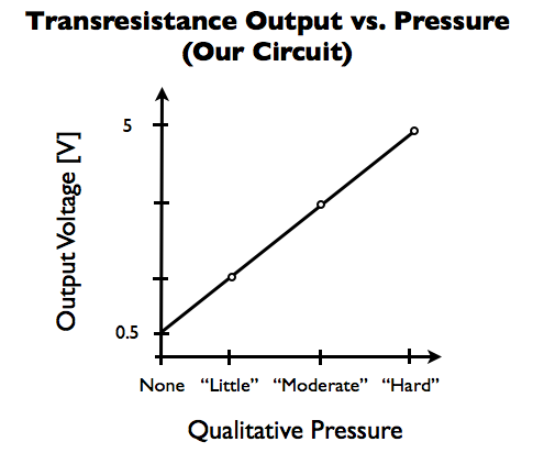
Our transresistance circuit (see CVC Electronics section) does give a useful output signal over the whole range of applied pressure.
