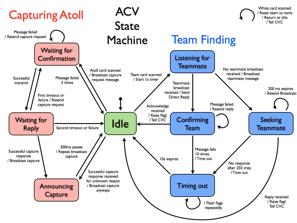
We confirmed that the team finding portion of our ACV state machine works today (without need of modification). We had confirmed that the atoll capture portion worked last week, but we were finally able to find other teams to pair up with today. Not much to show except for blinking LEDs and quick servo movements at this point, but they were the correct blinking LEDs and servo movements! This will all be more fun when we have flags... of some sort...
Here is the current plan for the main state machine on the ACV. It will run on the Xbee PIC and will be in charge of identifying our team and capturing an atoll (including sending all the messages required for these tasks). It does not interfere with any commands that need to be sent to the drive motors (even though these commands are sent on the same UART line used to talk to the Xbee, they have a different start byte and are not subjected to the 5Hz limit). We expect that this state machine will be responsible for all messages sent from the ACV.
The last two days of testing showed us that we really need to change some motor mapping according to the accelerometer. The previous motor mapping was based on the fact that I used the y-axis of the accelerometer as the power and the x-axis as the direction, and I used last quarter's mapping, shown below:

Using the accelerometer in the manner that we did yielded some very unfavorable results. For example, turning the controller completely to the left (keeping y-axis at equilibrium), yielded no turn as there was no power.
Our new motor mapping instead takes a polar coordinate approach, in which we use the "distance/radius" from the equilibrium (2.5V,2.5V) to determine power, and we use angle to determine direction. Using the newly derived power and direction, we can use the same motor mapping as last quarter with hopefully much better results. Below shows the new way to find power and direction:
Our new motor mapping instead takes a polar coordinate approach, in which we use the "distance/radius" from the equilibrium (2.5V,2.5V) to determine power, and we use angle to determine direction. Using the newly derived power and direction, we can use the same motor mapping as last quarter with hopefully much better results. Below shows the new way to find power and direction:

Unfortunately this approach requires the use of functions such arctan and sqrt. I tried using those functions given by math.h, but they ended up taking approximately 60% of program and memory space. The next inclination would be to use a lookup table. I used what I thought was the most minimal lookup table that was acceptable (26 x 26), which would yield about 10 points in each direction, and apparently the compiler could not "find space" for the variable. The last approach would be to make some approximations of the functions to derive power and direction.
We got the RFID card reader working. In its current state, the PIC receives information from the RFID board over UART, converts the ASCII bytes into hex nibbles, and reassembles the desired hex bytes and stores them locally in an array. We have yet to implement the SPI communication to send these bytes to the other PICs. Some interesting bits of the assembly code are:
Converting ASCII to Hex: This snippet takes an ASCII byte in the working register, and stores it as a hex nibble. ASCII numerals 0-9 are 0x30 to 0x39. ASCII letters A-F are 0x41 to 0x46. In this code, If the ASCII byte is above 0x40 (if it's a letter), 9 is added to the byte. So now A-F become 0x4A to 0x4F. We then mask the resulting byte with 0x0F to extract only the lower nibble. This gives us the desired value in hex.
ASCIItoHex:
          banksel   ASCII_Byte
          movwf     ASCII_Byte
;if ascii byte > 40, add 9
          sublw     0x40
          movlw     0
          btfss     STATUS,C
          movlw     9
          addwf     ASCII_Byte,W
;get lower nibble
          andlw     0x0F
          banksel   Hex_Nibble
          movwf     Hex_Nibble
Placing hex nibble: The above code places a hex character in the lower nibble of the byte. But half the time we want this to be the upper nibble. Instead of shifting the nibble by 4 bits, we use the neglected SWAPF to accomplish the trick.
          btfsc     RFIDNibbleIndicator,0      ;If this Nibble is High
          swapf     Hex_Nibble,f               ;make nibble MSNibble.