We are using two-color LEDs (red and green) to indicate the capture of atolls on the CVC. Even though there is a lot of room in our hamster ball, we prefer to keep the CVC to one PIC16F690 (no E128 because the CVC will be shaken and no other PICs for the sake of familiarity). Because all our sensor inputs and LEDs need to be controlled with one PIC, we implement LEDs using two daisy chained 8-bit shift registers (74HC595). The LED bits are shifted into the buffer using the serial clock (SCK on SSP), and when the shifting is finished we enable RCLK to output to the LEDs. The circuit looks as follows:
The last two days of testing showed us that we really need to change some motor mapping according to the accelerometer. The previous motor mapping was based on the fact that I used the y-axis of the accelerometer as the power and the x-axis as the direction, and I used last quarter's mapping, shown below:
Using the accelerometer in the manner that we did yielded some very unfavorable results. For example, turning the controller completely to the left (keeping y-axis at equilibrium), yielded no turn as there was no power.
Our new motor mapping instead takes a polar coordinate approach, in which we use the "distance/radius" from the equilibrium (2.5V,2.5V) to determine power, and we use angle to determine direction. Using the newly derived power and direction, we can use the same motor mapping as last quarter with hopefully much better results. Below shows the new way to find power and direction:
Unfortunately this approach requires the use of functions such arctan and sqrt. I tried using those functions given by math.h, but they ended up taking approximately 60% of program and memory space. The next inclination would be to use a lookup table. I used what I thought was the most minimal lookup table that was acceptable (26 x 26), which would yield about 10 points in each direction, and apparently the compiler could not "find space" for the variable. The last approach would be to make some approximations of the functions to derive power and direction.
After yesterday's check off (having the CVC xbee talk to the ACV xbee), we decided to take it one step further, having the CVC actually send motor commands over to the ACV. For our drive train functions, since we plan on having one "orb" to control everything with an accelerometer, luck would have it that our motor mapping functions from 218b fit very nicely with this control system (http://218b.weebly.com/software.html). For this prototype we used one potentiometer to act as the forward and backwards command (a la y-axis of accelerometer) and another potentiometer as the turning (x-axis of accelerometer). It was a bit tricky to control the boat, but the hamster ball should work a lot better!
Please see the videos below to see our boat on its RC maiden voyage (unfortunately we did not have champagne). This was a quick and dirty prototype (lots of duct tape), but we definitely got a feel for how easy the boat is to control, and it also showed us that some tweaking needs to be done in the motor mapping.
<
We've arrived at a new set of inputs and controls for our CVC. Since we've mostly ruled out a propulsion mode that we were secretly considering (more on that at a later date), we don't have much of a use for the balancing plank that we presented at design review.
Our new control method consists of a large (13" diameter) plastic sphere that the user holds. The user will tilt the sphere forwards and backwards to control speed and side to side to control turning. The user will squeeze the sphere harder to amply the boat's speed, or he will hold the sphere gently for precise movements. The user will calibrate the accelerometer by shaking the device to initialize a calibration sequence.
The sensors we will use are:- 2-Axis ADXL203 (pdf) accelerometer -- this senses the forward/backwards and side-to-side tilt of the sphere for driving the boat.
- Force Sensing Resistor (2128260 at Jameco) -- Two of these, one on each the left and right side of the sphere, will detect that the user is holding the sphere. They will also measure how hard the user is squeezing the sphere for amplifying the boat's speed.
- Optical Shake Switch -- Inspired by tilt switches, we will make our own "shake switch" that will consist of an opaque weight inside a tube. When shaken, the weight will travel to the top of the tube and interrupt an IR LED/Sensor pair. This action will initialize calibration of the accelerometer.
Today's concept was to roll out a bunch of iterations for our boat design. We started with a very basic 2D platform with slots to accommodate 6-inch paddle wheels. (1) The first iteration of the platform was quite slow because it had a high water level with respect to the platform (about half inch), so the paddle wheel was dragging a lot of water. (2) The second iteration consisted of us putting a thin piece of foam underneath it. This made the paddles submerge less and consequently made the boat faster. (3) We noticed that the paddle wheel kicked up water in its slot, leaving the water nowhere to go but back onto the paddle wheel, substantially slowing us down. We cut out slots to accommodate these streamlines, making the platform look like a boat with two pontoons. This made the boat a whole lot faster. (4) There was a lot of rippling happening at the front of the boat, so we put a draft at the front of the boat, which made it ride a lot smoother.
We got the RFID card reader working. In its current state, the PIC receives information from the RFID board over UART, converts the ASCII bytes into hex nibbles, and reassembles the desired hex bytes and stores them locally in an array. We have yet to implement the SPI communication to send these bytes to the other PICs. Some interesting bits of the assembly code are:
Converting ASCII to Hex: This snippet takes an ASCII byte in the working register, and stores it as a hex nibble. ASCII numerals 0-9 are 0x30 to 0x39. ASCII letters A-F are 0x41 to 0x46. In this code, If the ASCII byte is above 0x40 (if it's a letter), 9 is added to the byte. So now A-F become 0x4A to 0x4F. We then mask the resulting byte with 0x0F to extract only the lower nibble. This gives us the desired value in hex.
ASCIItoHex:
          banksel   ASCII_Byte
          movwf     ASCII_Byte
;if ascii byte > 40, add 9
          sublw     0x40
          movlw     0
          btfss     STATUS,C
          movlw     9
          addwf     ASCII_Byte,W
;get lower nibble
          andlw     0x0F
          banksel   Hex_Nibble
          movwf     Hex_Nibble
Placing hex nibble: The above code places a hex character in the lower nibble of the byte. But half the time we want this to be the upper nibble. Instead of shifting the nibble by 4 bits, we use the neglected SWAPF to accomplish the trick.
          btfsc     RFIDNibbleIndicator,0      ;If this Nibble is High
          swapf     Hex_Nibble,f               ;make nibble MSNibble.
Here's an idea for how we can set up all our communications between PICs. Dashed lines are connections I'm not 100% sure we need (and the dotted lines are RF communication). One interesting idea is having the output of the PIC that reads the RFID reader connected to the input of the Security Controller. The Security Controller would output to a second pic, and this PIC would report to the main processor on board the ACV. We might be able to get rid of the PIC that interfaces with the Security Controller by putting the Security Controller and the Xbee on the same EUSART lines. Doing so may or may not be easier.
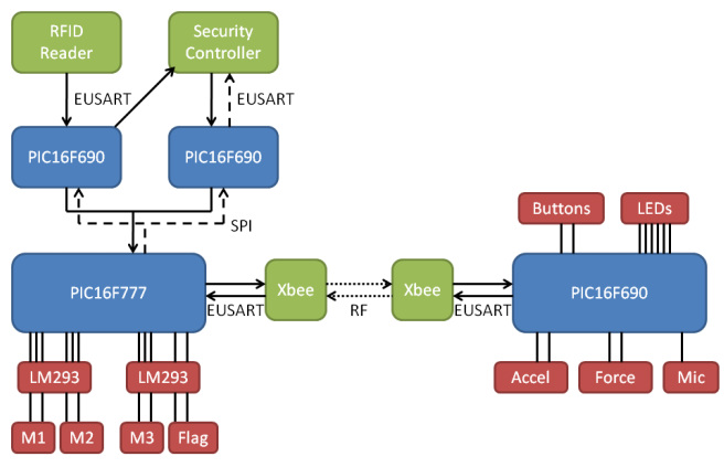
Diagram for a communications concept.

We might be due for a team name change.
We had to get these when we saw these on Tanga.com. Inspired by our favorite processor, and in opposition to our potential opponents "EPIC WIN".


