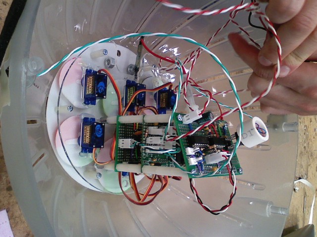
Our CVC is coming together beautifully. We ditched the foam piece in the center and now have everything hanging off standoffs that are attached to the servo plate (which is attached to the score board front face). You can faintly see the color indicator wheels that we attached to the servos. Wait until you see them in action!
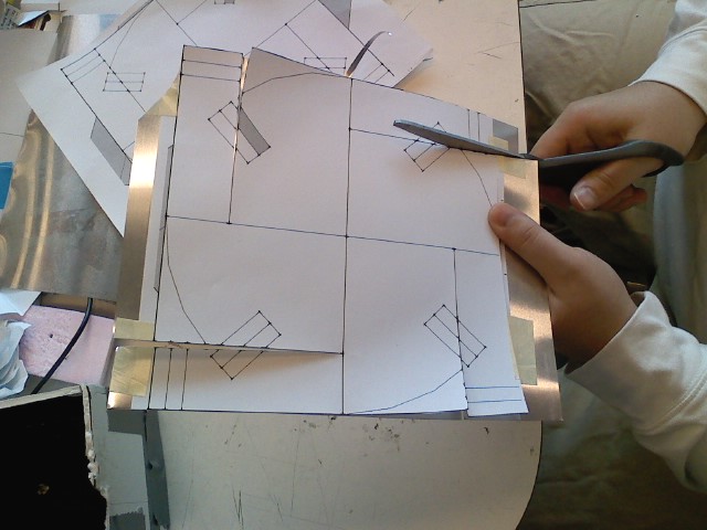
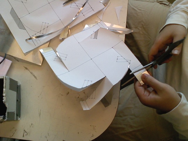
Below are pictures of how we make the paddle wheels. We start with a template and tape it on to the aluminum sheet. We then cut the appropriate strips that are subsequently bent to make perfect paddle wheels. We sandwich two of these together to get a very robust form factor.
Well we tested our LEDs outside for the first time yesterday, and when they were nearly invisible due to the sunlight, we got super bright ones to test today. These new ones (part number, anyone?) are ultra efficient, but are still barely visible in direct sunlight. Our verdict is that LEDs are a no-go for the CVC. Our current plan is to have 6 servos in the CVC (one for each atoll, one for the team color) that will spin color wheels to the appropriate positions.
We were initially worried about how this would affect our meeting the CVC's 8-hour battery life requirement, but found that an unactuated servo (i.e. if we set a position and then leave it there) only draws about 6mA of quiescent current. This equates to way less of a power draw than our LEDs would have been, anyways.
We confirmed that the team finding portion of our ACV state machine works today (without need of modification). We had confirmed that the atoll capture portion worked last week, but we were finally able to find other teams to pair up with today. Not much to show except for blinking LEDs and quick servo movements at this point, but they were the correct blinking LEDs and servo movements! This will all be more fun when we have flags... of some sort...
To indicate team color we use two servos on the ACV to raise (current unmade) flags. See the video below.
Today we brought an atoll down and captured it with out boat. Being agile definitely helped a ton, as it sometimes took more than one try to actually get close enough to the RFID card. This is so awesome!
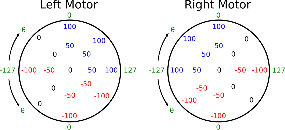
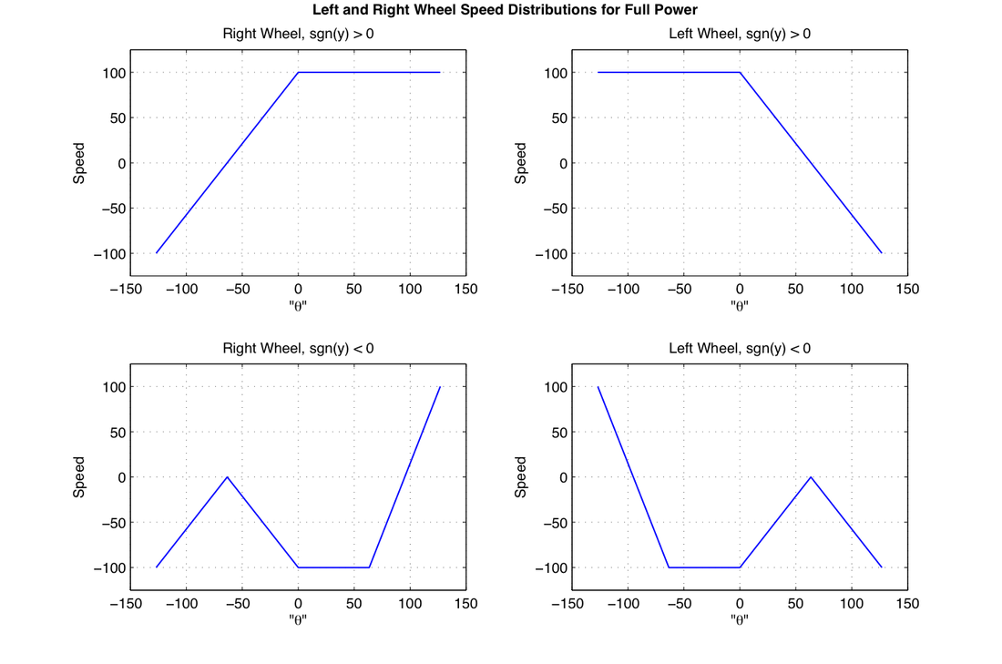
The last motor mapping did not give us the behavior we wanted. For example, if the controller is pointed forward and right you want the left motor at 100 and right motor at 0; this behavior was shown in the old motor mapping. If the controller is pointed completely to the right, you want the left motor at 100 and right motor at -100; this behavior was shown in the motor mapping as well. The controller is pointed back and to the right, you would want the right motor stopped and left motor at -100 (so the rear pointed to the right, like a car would); this behavior was NOT shown in the old motor mapping.
Instead the motor mapping should look something like this:
This translates into the following graphs, where if you can see, the reverse direction (sgn(y) < 0), which is quite complicated. These graphs are only for the case of full power (outer radius). We scale these graphs by the appropriate proportion of the full radius/power.
Update: This motor mapping (yet again) was not what we were looking for. The transitions in the reverse direction are just too harsh for us. We will work on another algorithm...
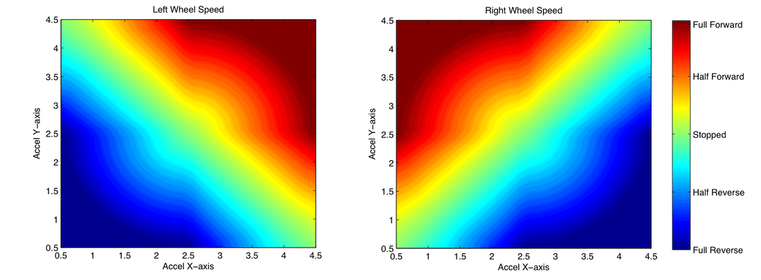
For fun, we can also directly map the x and y accelerometer readings straight to the wheel speeds, shown below:
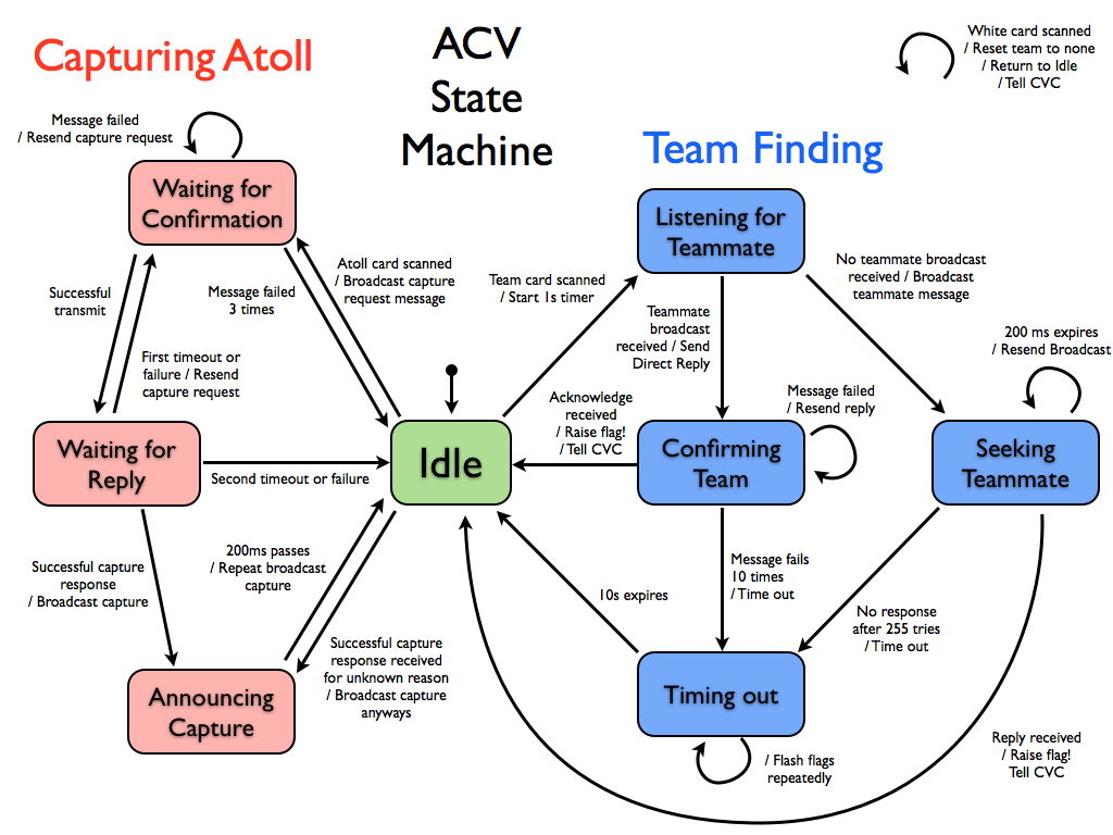
Here is the current plan for the main state machine on the ACV. It will run on the Xbee PIC and will be in charge of identifying our team and capturing an atoll (including sending all the messages required for these tasks). It does not interfere with any commands that need to be sent to the drive motors (even though these commands are sent on the same UART line used to talk to the Xbee, they have a different start byte and are not subjected to the 5Hz limit). We expect that this state machine will be responsible for all messages sent from the ACV.
Turns out that mapping the motors is not that simple in C-programming, since our power function depended on the use of a square root, and the direction depended on finding arctan() to determine angle. I tried using math.h (even though it takes up a lot of space) and it took a whopping 5ms to calculate arctan() (sqrt was in that same range). We set out to make approximations that were based on simple polynomial expansions and would only take ints (not floating points).
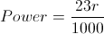
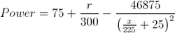
For finding the square root, we do the following, where r (sqrt(x^2+y^2)) is the number we want to find the square root of (if you notice the first function will give us a dead-band, which we might want, since for values of x less than approximately 40, the int becomes truncated. Coefficients are based on the fact that the A/D converter will give us numbers between 0 and 255 for both x and y coordinates, which we translate to -127 to 127):
For x < 1000
For x > 1000
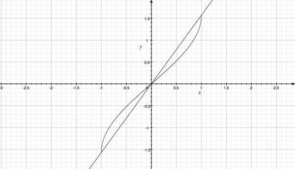
For finding direction, instead of trying to be linear with respect to theta, we use cos, which gives us the same extreme limits, but gives us less sensitivity near the equilibrium position. This might or might not be an undesirable effect; we will have to see, but this is a lot easier to calculate. The graph below shows direction being linear with theta, and the difference of using cos.